Special developments
Testbenches are used during development to optimise and test prototypes and new designs. Afterwards, the nominal properties of parts are tested under the most realistic conditions possible during series production. This ensures sufficient product quality. Our test bench solutions provide manufacturers and suppliers alike with well-proven and powerful tools.
-
TESTBENCH CONSTRUCTION, INDIVIDUAL TESTBENCHES
test benches for component testing
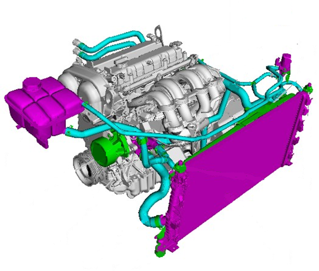
3D CAD components for testbench 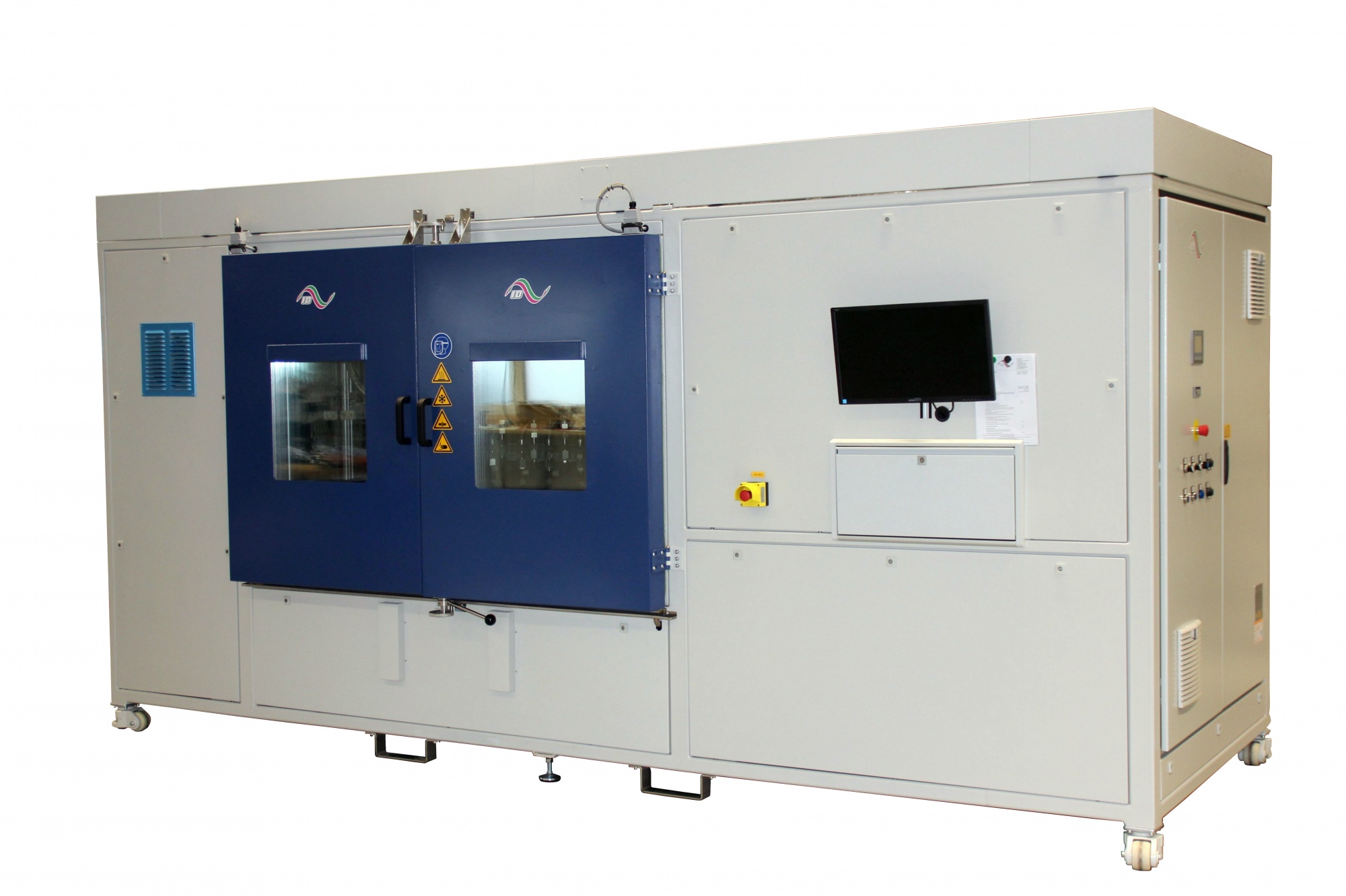
Pressure Cycling TestBench for Components of Cooling Circuit with 3D Motion Unit Features:
· Testbench designed for pressure tests on various hose components of the automotive cooling water circuit
· Pressure change testbench with 3D-moving unit. 3D-moving unit installed under the test chamber
· testbench for static and pulse pressures in the range of -0.5 to max. 10bar
· Heating of the testbench chamber with monitoring and limitation of the max. temperature
· Automatic leak detect and leak test (with automatic switching off, of failed test parts)
· Automatic backflow pump for coolant leakage
· Windows / LabView based control unit and data recording
Dimensions testbench: 4700mm x 1900mm x 2500mm (w x h x d)Inner dimensions of testbench chamber: 1800 x 1000 x 1000mm (w x h x d) Rated power: 82 kW
· Operating fluid: Glycol / Water
· Pressure range: up to 10 bar
· Main flow: up to ca. 40 l/min per test parts (max. 400 l/min with 10 channels)
· Range of movement: X- axis: max. ±40mm max. 2,0Hz
Y- axis: max. ±40mm max. 2,5Hz
Z- axis: max. ±40mm max. 3,0Hz
· Waveform pressure: Sine, Trapezoidal, Static
· Temperature range fluid: -40°C … +150°C
· Temperature range chamber: -40°C … +150°C
· Number of test channels in testbench: 10
· Examples for practicable test specifications:
o VW 78007, TL 81165, TL 874 (4.4)
o TL 82002, TL 52682, TL886, TL889, TL 82086
o TL 52361 (6.1.1/6.1.2), PV 1712 (Ag-99-03),
o GMW 3155, GMW 18152, GMW 18165
o PTL 14052-A1203, PTL 14100-A0911
o BMW LH 10356681 (10.5), LH 10757369 (6.), QV 17004
o BMW LH 7823444.6, BMW LH 10591317, LH 10274837
o Daimler M139 (2), M177 (2)
o DIN 73411-2 [39]
example for mounting in the testbench:
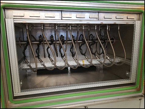
Typical test setup in the testbench chamber with linear motion unit -
AUTOMATED MEASUREMENT PROCEDURES
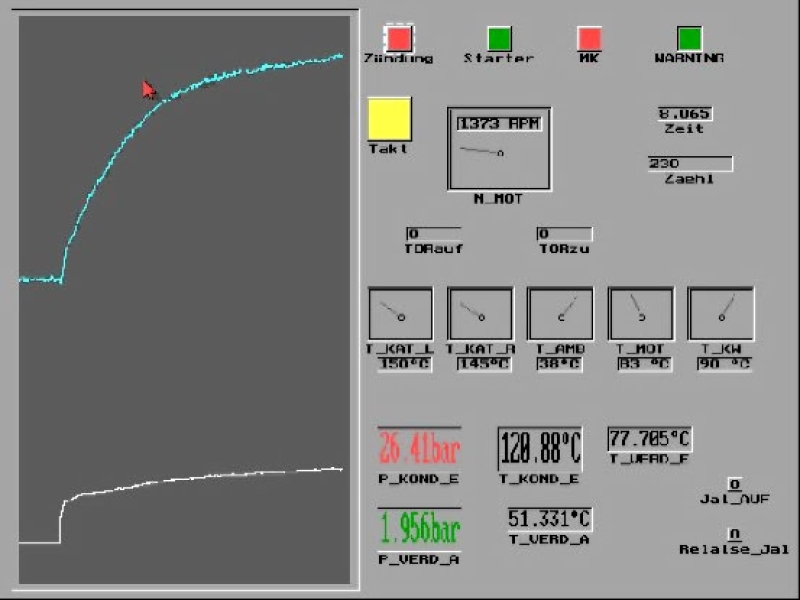
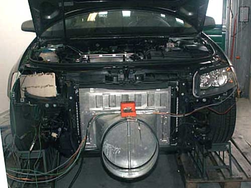
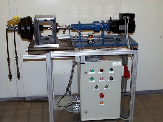
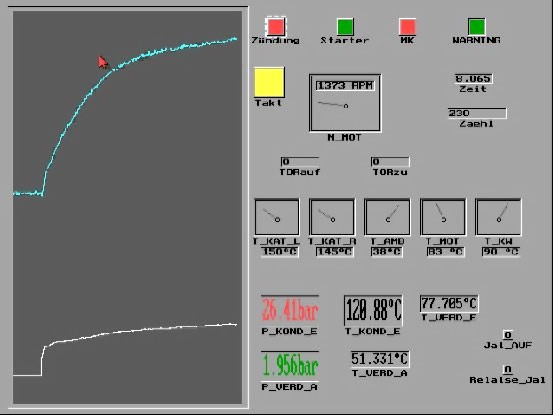
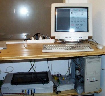
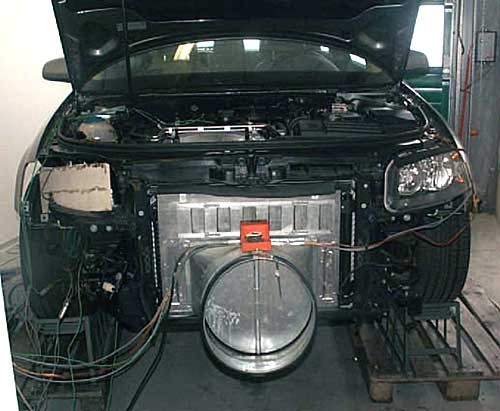
The example shown below shows a so-called continuous garage run to check the gas tightness of air conditioning lines in the vehicle. Here, certain pressures and temperatures are achieved in the vehicle's air conditioning system for over 800 hours (1 hour run, 1 hour break). The room temperature should be kept at approx. 40 ° C. The control and regulation takes place via a separate computer with control electronics and adapted software.
The setting and regulation of the required pressures and temperatures in the air conditioning circuit takes place via flaps on the air inlet in front of the air conditioning condenser, which are opened and closed according to requirements. The motor speed is kept constant, and the room temperature is also regulated depending on the operating state.
-
ELECTRONICS SPECIAL DEVELOPMENTS
EPROM copy protection
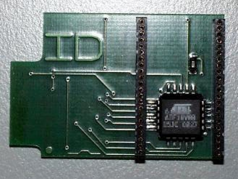
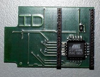
The backup of software versions, often laboriously developed at great expense, against pirate copiers is becoming more and more important and not infrequently a question of survival for the active companies. The example shown below shows an EPROM copy protection for engine control units.
The intermediate board shown is used to protect a developed chip tuning from pirate copiers. For this purpose, the EPROM is built on the intermediate board and the intermediate board is inserted into the control unit in place of the EPROM. There is a chip on the intermediate board that encrypts the data record. We have developed a special encryption program to generate this encrypted data record. It is particularly important that this program can be adapted for each customer. Thus, the same codes result in completely different encryptions for different customers.
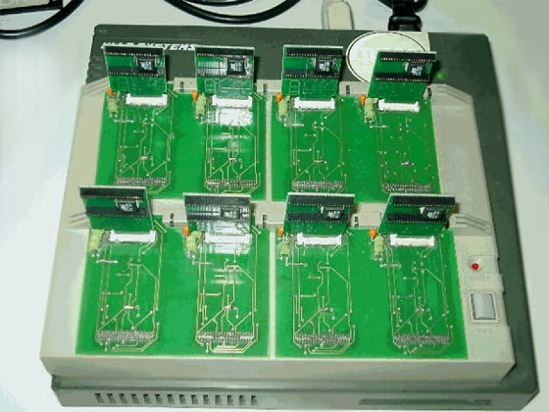
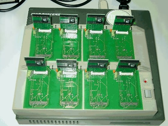
In order to give every customer the opportunity to freely assign their code, we have designed the intermediate boards in such a way that they can be programmed with the corresponding code at the customer's site. We have developed a special holder for a programming device for this purpose.
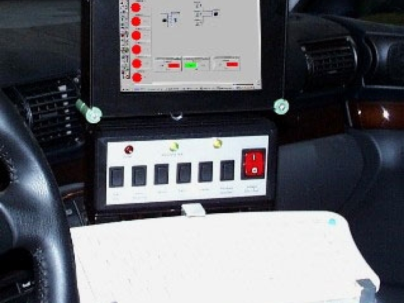
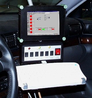
Special screens, control units
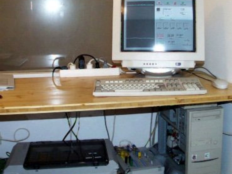
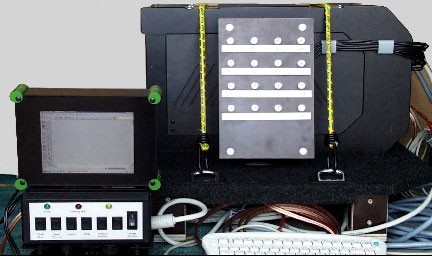
The aim here was to create a control unit for measuring computers and to connect it to a 6.4 "TFT screen that was as light as possible. The screen is also a self-made design and, with a total weight of 1kg, is lightweight with a very robust design. The control unit enables here For example, in connection with the measurement data acquisition and evaluation software DasyLab, operation in the vehicle without using a keyboard.
With this control unit, predefined settings and display settings can be called up, as well as the start, stop and storage of the measurement. When the power supply is switched on, the computer automatically starts the required measurement program and is then ready for measurement. Windows is also closed at the push of a button and the computer is shut down. The state in which the measuring system is currently located is signaled via 3 LEDs. This means that even less specialized users can process standard scopes of measurement.
The connection to the actual measuring system can be made either via digital I / O or via the RS232 of the computer used and can therefore not only be used in conjunction with DasyLab. For the more experienced user, a keyboard can also be added as an option.
DC / DC converter for measuring systems
Today's modern measuring systems have mostly battery-backed power supplies, especially for mobile use. Occasionally, the user also creates separate buffering. With these systems, however, it is often only possible to charge the batteries externally, as no suitable charging electronics are integrated in the device, which enables the device to be operated and charged at the same time with the on-board voltages, which can sometimes drop to approx. 10VDC over a long period of time make possible.
In the present case, we have created a DC / DC converter whose output voltage is continuously adjustable from 12VDC to 17VDC. This makes it possible to adapt to the charging characteristics of different battery types and different battery nominal voltages. Since, in the case of subsequent installation of batteries or subsequent conversion to parallel operation, diodes also have to be built into the device in some cases, the corresponding additional voltage drops can also be compensated for.
Electronic drives: AC / DC
The converter below for a mobile shaker (three-phase asynchronous motor) has been expanded with additional electronics to enable longer (up to 1000 sec.) And temporally different start-ups of the connected exciter, which could not be achieved with the standard device.
In addition, the speed of the exciter (not shown) is output in digital form as a TTL signal and as an analog DC voltage.
For other applications, see also the pulse pressure test bench (see the testing technology brochure), where a regulated servo drive is used to implement predetermined pressure curves, as well as, for example, control of an automatic gearbox by means of a switch using a stepper motor control
-
IMPACT DEVICES FOR INDUSTRY, e.g AVIATION, RAILROAD
mobile impactor (gasgun Next Generation)
New materials such as hybrid materials GLARE (Glass Fibre Reinforced Aluminium or Glass Laminate Aluminium Reinforced Epoxy) or "carbon-fibre-reinforced plastics" (CFRP) and "glass-fibre-reinforced plastics" (GFRP) have been displacing traditional materials such as aluminium for some time or replacing them on exposed elements due to their properties. The advantage in comparison to aluminium - until now the standard material in aircraft construction - lies in its better burn-through and impact behaviour. Another advantage over aluminium is its behaviour towards cracks. Cracks are "bridged" by the glass fibre layers, so that the crack speed decreases with increasing crack length, whereas with aluminium the crack speed increases strongly. Therefore, it is used primarily because of its behaviour towards cracks in the upper fuselage area and on the underside of the wing, as well as in the nose area of the vertical stabiliser and in the cockpit area due to its impact behaviour.
Other areas of application for hybrid materials are body construction for railways (locomotive construction) and the automotive industry.
In order to be able to specifically introduce damage into the structure and assess the type of damage (mainly in the form of delamination), ID Lindner developed a mobile device (mobile impactor or "mobile gasgun") in collaboration with Airbus, with which specimens and entire components can be specifically tested with predefinable energies and impact heads. This allows damage caused by low-velocity impacts such as hail or falling tools ("tool-drop") to be reproduced.
Features:
· Designed for material tests in the aviation and the railway sector
· Designed for one-man operation
· mobile testing FRP composite (Fiber reinforced polymers and plastic) or GLARE
· Material testing by generating an impact with a defined energy level using compressed air
· Available with different projectiles (different weights, different projectile heads)
· Effective energy adjustable from 3 to 140 Joule (250J at request), for connection to the in-house compressed air supply
· Analysis and display directly on the built-in touch screen (4.3", 480x272 pixels)
· Measurement data storage on SD card
· Data recording with 50kHz sampling rate for indentation, velocity, acceleration
· A mobile compressor is available on request if no compressed air supply is available
· Dimensions Impactor: 270 x 600 x 200mm (w x h x d)
· Weight: 10 kg
· Impact energy: max. 140 J at approx. 6 bar
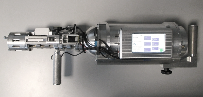
gasgun next generation 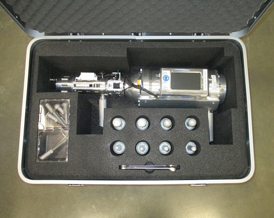
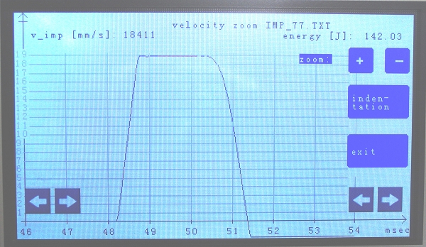
transport box with different projectils and projectil heads On-Site evaluation of energy:
grphical evaluation of the velocity at impact time, calculation of projectile energy
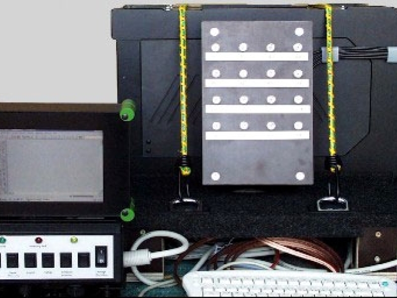
Impact drop system in the aircraft industry
In order to be able to introduce new materials in the aircraft industry, such as fiber-reinforced plastics / aluminum, their behavior on unforeseen impacts must be known. For this purpose, an existing impact case system of a European aircraft manufacturer was upgraded so that the force curve occurring during the impact and the path and speed curve can be scanned, measured and documented at high frequency with 50 kHz using a load cell that falls along with it.
The impact cap, drop weight and drop height can be freely selected within certain limits. Another fall system was newly equipped with a falling acceleration sensor and also non-contact distance and speed measurement. All measurement data are also sampled at 50 kHz. Automated operation was implemented for both fall systems. The control takes place with a corresponding measuring software with which the data can be recorded, visualized and saved. The measurements are made with a USB measurement box.
Impact energy, energy dissipation, speed curve and depth of penetration during the impact as well as when jumping back can be evaluated in this way.
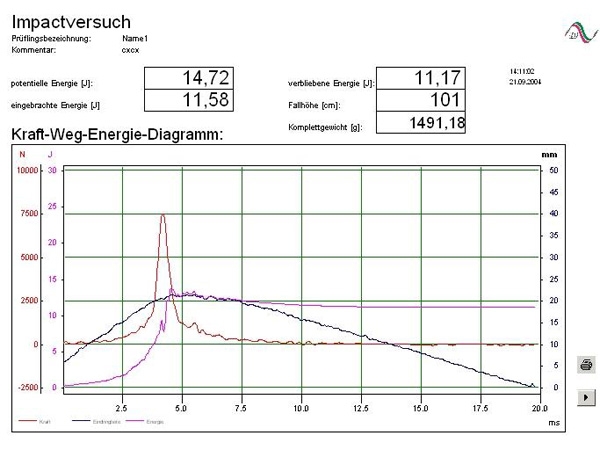
force, indentation, energy diagram -
CONFIGURATION OF MEASURING SYSTEMS
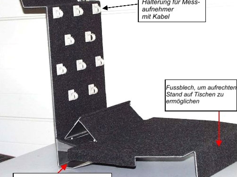
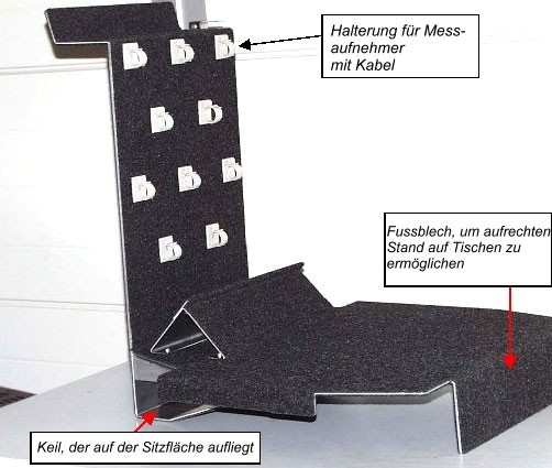
Configuration of measuring systems
Here, for example, for travel measurements, a safe option is offered to securely attach the required measuring system to the passenger seat. The fastening of the measuring system on the bracket is created individually in each case. The assembly of the entire measuring electronics including transducers and / or computers (laptop) can be done quickly and easily. For use in left- and right-hand drive vehicles, the measuring system can also be rotated (not shown). It is secured using the seat belts. Appropriate clamps are provided to hold the sensors (e.g. acceleration sensors) with cables.
-
SIMULATION
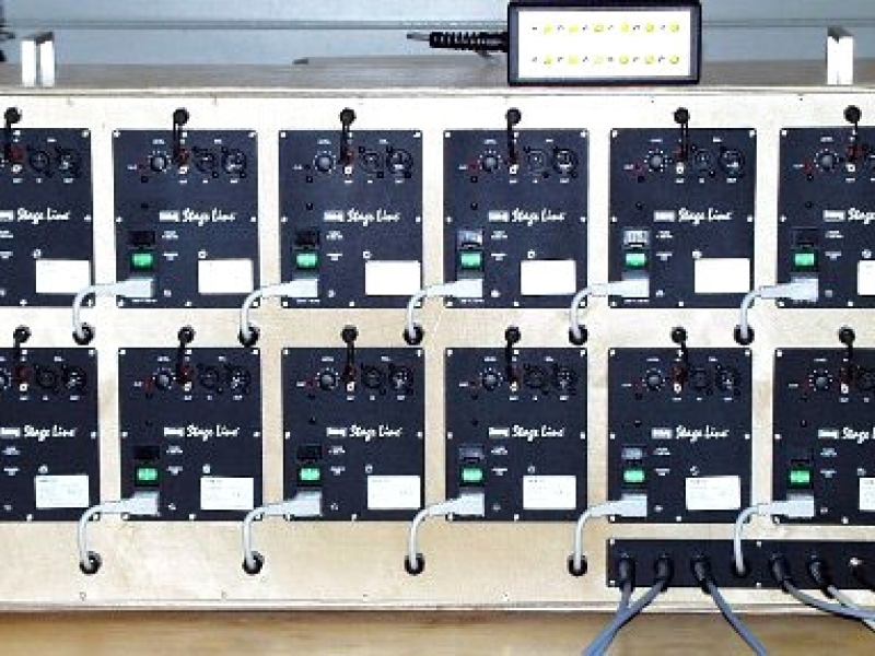
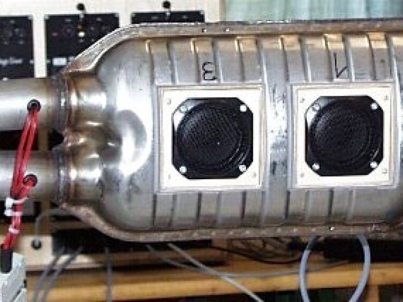
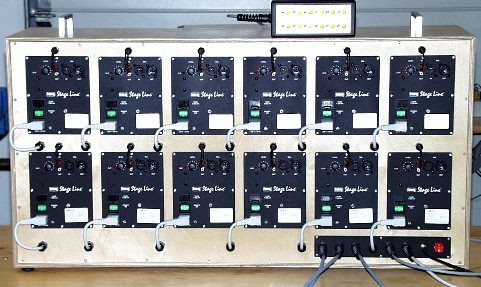
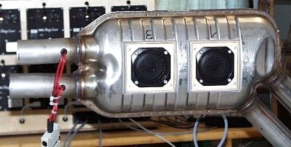
simulation
Loudspeaker installation in an exhaust system, for simulation (including control and amplifier). The loudspeakers are each connected to an amplifier and can be individually switched on and off using a remote control. As a result, it is subjectively and technically possible to determine the origin of a stimulus (frequency) in the interior of a vehicle (can be used e.g. for sound design).
-
TESTBENCH COMPONENTS, TEST SETUP
Test bench components, test setups
Electromechanical actuation of a brake booster for dynamic control of the brake pressure in testbench applications
brake testbench
We have raised your interest? Let us quote you an offer for your individual testbench without obligation:
for contact